 |
FLAA Users Manual
1.3
|
|
FLAA Users Manual
1.3
|
flaa is a control program for use with the RigExpert AA-xxxx series of antenna analyzers.
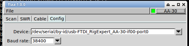
The program always starts with a display of the configuration tab.
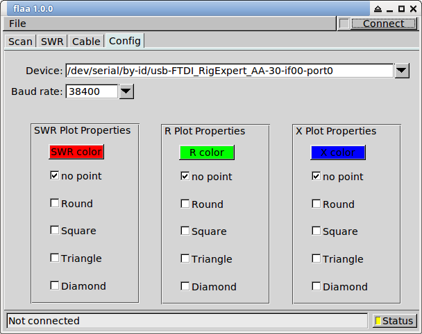
The color and data point plotting for the x-y plots can be individually configured.
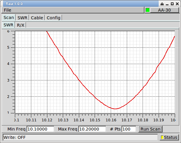
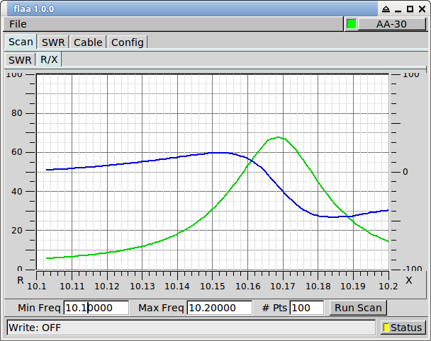
The most common use of the antenna anlyzer is to measure standing wave ratio, SWR, and input impedance, Z, either over a frequency range or on individual frequencies. The result is plotted as either the standing wave ratio, SWR, or the real and imaginary components of the input impedance.
Continuous measurement of SWR can be made on selected bands/frequencies. The band specification is simply for convenience and the frequency can be set to any within the range of your RigExpert.
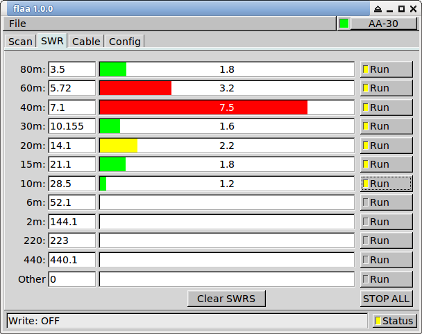
Shown for measurements on my 6BTV vertical. Either the position of the 40 meter trap needs to be adjusted, or the trap itself needs to be overhauled. I'm guessing it has a blown capacitor.
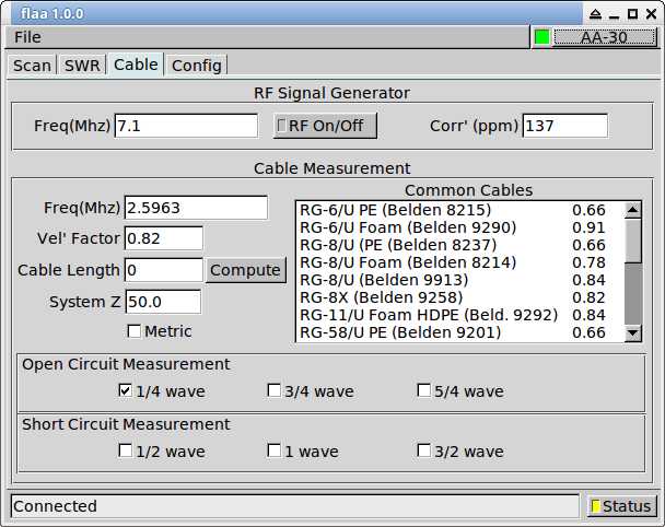
Either enter the cable velocity factor, or select from one of the common cables control. The input impedance to an open circuit coaxial cable will be 0 + j0 at 1/4, 3/4, 5/4 ... wavelengths. An open circuit cable will be at 1/2, 1, 3/2 ... wavelength.
Open circuit scan is show here for a 0.1 to 30.0 MHz; RG-8/U cable, length ~= 77 feet.
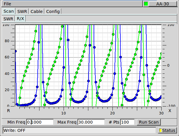
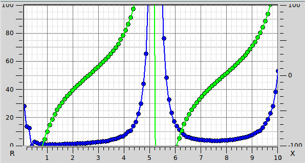
2.6 MHz (1/4 wave point) and/or 7.9 Mhz (3/4 wave point).
The AA-xxx antenna analyzer can be used as a signal generator. You should calibrate the units reference oscillator for improved accuracy when used as a signal generator. Once calibrated the correction will be applied to all measurements of SWR, Impedance, etc.
The "Corr' (ppm)" is the correction factor in parts per million that needs to be applied to each frequency value, both sent and received.
You can determine the ppm correction factor a number of ways.
Using the RF On/Off function in flaa, produce a number of signals across the operating range of the unit. The AA-30 is 3-30 MHz.
Measure the generated signal on a calibrated receiver. Plot the measured versus generated using the differences. The slope of the error versus frequency is the ppm error. Measurement made using fldigi's "Analysis" modem. The AA-30 h/w uses a dds driven by a single reference oscillator. Hence the nice linear relationship between frequency and error.
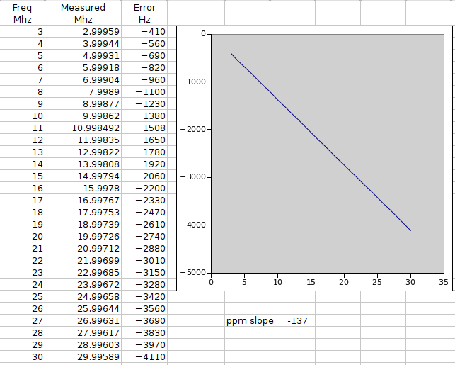
Enter the ppm correction as the negative of the measured slope, i.e. -137 for the above calculation.
For a given amateur band, set the transceiver to a specific frequency on USB, for example 7.099.000. Monitor the transceiver audio using the fldigi Analysis mode. Set the AA-xxx to 1000 Hz above the transceiver USB frequency, i.e. 7.100.000 MHz. Adjust the AA's RF generator setting to place the AA-xxx signal at 1000 Hz on the waterfall. You will have to toggle the RF On/Off to reset the AA DDS for each change in frequency and/or ppm.
Tune the transceiver to a WWV signal, perhaps 10 or 15 MHz. Set the AA to the same frequency and adjust the ppm setting for zero beat between the two signals. As in 2, you will have to toggle the AA RF On/Off.
The scanned impedance values can be saved to a comma separated file. A saved value set can be imported back into flaa and displayed on the SWR and R-X plots.
flaa has been successfully tested on these models:
| AA unit | Tested by |
|---|---|
| AA-30 | W1HKJ |
| AA-54 | AB2ZO |
| AA-520 | KB1OIQ |
| AA-600 | N2YQT/AA3RK |
| AA-1400 | KL0S |
Notify the author, W1HKJ, w1hkj@bellsouth.net, if you are successful with other models.
flaa has not been successfully tested with the RigExpert Zoom models.
 1.8.11