 |
flrig_help
2.0.04
|
|
flrig_help
2.0.04
|
Select the transceiver with the "Config / Setup / Transceiver" menu item.
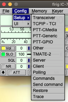
Each of the menu items will open the configuration dialog to the respecive tab:
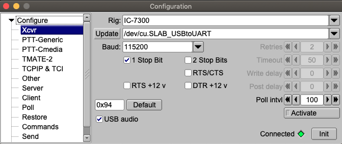
Select the rig in use from the "Rig" combo box.
The default values associated with that transceiver will be preset for you. These have been verified by the test team but might require some tweaking for your particular h/w.
If required by the hardware interface, set either RTS or DTR to +12 if interface power is derived from the serial port.
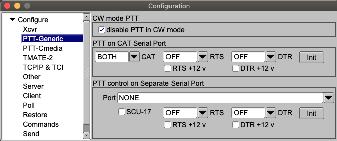
Select CAT PTT if your transceiver supports a CAT command for PTT on/off. This control will default to checked if CAT PTT is supported.
You may prefer to use h/w PTT signaling instead of CAT PTT. The h/w PTT may be shared with the CAT serial port. Note that both RTS/CTS handshake and RTS PTT cannot both be used on a single serial port.
Your PTT h/w control may also make use of a second serial port. If that port is the secondary serial port of the SCU-17 then you must also enable the "Serial Port is SCU-17 auxiliary" control.
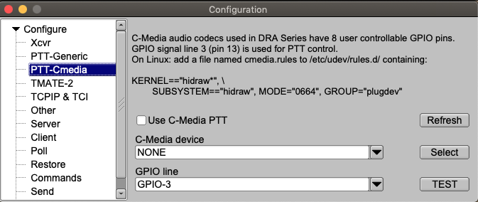
Cmedia audio codec chips are used in a number of inexpensive USB audio thumbnail devices.
It is also used in the DRA@ series of sound card adapters. The DRA is a radio optimized sound card used to connect a two-way radio to a computer for digital communications. The DRA-Series digital radio adapter is used for Packet Radio or other digital programs and applications like VARA-FM, VARA-HF, SoundModem or fldigi.
All RA Series radio adapters include GPIO support. The Cmedia device supports 4 unbuffered input/output lines, GPIO-1 ... GPIO4. GPIO-3 is used to drive a fully buffered and deadman protected PTT circuit. All DRA Series radio adapters include a Heartbeat Monitor. When the Cmedia device is reading or writing audio data, the HeartBeat status LED (HB) will be flashing. If everything is okay, (HB LED is flashing) a Blue LED called "COMM OK" illuminates. If the HB LED stops flashing because the radio adapter or the computer/appliance has failed, or the software has stopped reading or writing audio data, the Blue COMM OK LED goes out. The Blue LED indicates the health status of the system, and illuminates when everything is okay.
The PTT line on any DRA Series radio adapter is interrupted with the failure of this health status. This function will kill the PTT line the audio stream is interrupted. This will occur if fldigi and similar modem program is not reading/writing audio data.
The circuitry was designed to operate correctly no matter if the Heartbeat has stuck in the on or off state.
The PTT type, the device and the GPIO line must be selected. If multiple C-Media devices are discovered they will enumerate as C-Media-A, C-Media-B, etc.
You must test the selected interface as it is not possible to know which is the correct one for the DRA interface. Pressing the TEST button will cause the PTT line to rapidly toggle for a period of 2 seconds. This will cause the RED PTT led to flash and the transceiver PTT to toggle on and off.
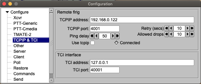
TCPIP
flrig is can communicate with a transceiver that provides CAT control over ethernet. It can also communicate with a remote computer with a software serial to ethernet converter such as SOCAT. Both the device address and port must be specified.
TCI
Transceiver Control Interface was developed by Expert Electronics company, for advanced connection between the ExpertSDR2 and third-party software. TCI has all required control commands similar to CAT system, but even more, it can transfer IQ-streams from the ExpertSDR2 to client applications. The ExpertSDR2 is the only TCI capable transceiver.
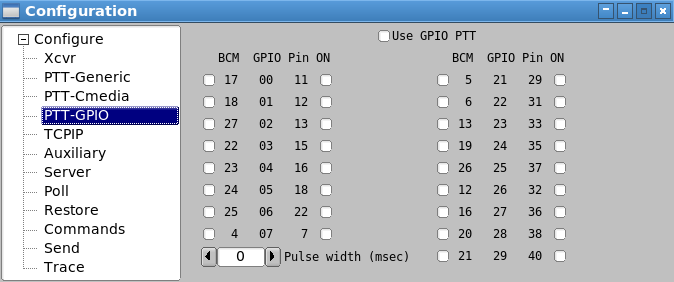
The Pi series of miniature computers offer a large array of possibilities for controlling devices. It has a array of General Purpose Input Output, gpio, lines of a 40 pin in-line header. 17 of these gpio lines can be used for things like push-to-talk. There are several add on boards for the Pi3 and Pi4, such as the NW Digital Radio UDRC-II, that has a full interface for digital operations, including PTT and audio codecs.
Access to hardware ports is always limited to the user who either is root or has root privileges. setuid and setgid (short for set user ID upon execution, and set group ID upon execution, respectively) are Linux access rights flags that allow users to run an executable with the permissions of the executable's owner or group respectively and to change behaviour in directories. They are often used to allow users on a computer system to run programs with temporarily elevated privileges in order to perform a specific task. While the assumed user id or group id privileges provided are not always elevated, at a minimum they are specific.
It is possible to give full gpio access and control privileges by elevating flrig with setuid root. But this is not advisable as flrig is also granted access to both serial and network services. There is a way to provide the access via a second program that does have the elevated privilege
This is a copy of material at
https://projects.drogon.net/raspberry-pi/wiringpi/download-and-install/
for installing WiringPi which includes a really nice utility called gpio.
To obtain WiringPi using GIT:
$ git clone git://git.drogon.net/wiringPi
If you have already used the clone operation for the first time, then
$ cd wiringPi
$ git pull origin
Will fetch an updated version then you can re-run the build script below.
To build/install there is a simplified script:
$ cd wiringPi
$ ./build
The build script will compile and install it all for you. It does use the sudo command at one point, so you may wish to inspect the script before running it.
Test wiringPi's installation
run the gpio command to check the installation:
$ gpio -v
$ gpio readall
That should give you some confidence that it’s working OK.
WiringPi is released under the GNU Lesser Public License version 3.
flrig uses the gpio program for initializing the gpio port, which also happens to the change the privilege of the temporary sys file for setting the port state.
Read the man document for gpio
GPIO is  a  swiss  army knife of a command line tool to allow the user
easy access to the GPIO pins on the Raspberry Pi and the SPI A/D and D/A
converters on  the  Gertboard.  It's designed for simple testing and
diagnostic purposes, but can be used in shell scripts for general if
somewhat slow control of the GPIO pins.

It can also control the IO's on the PiFace IO board and load the SPI and
I2C  kernel  modules if required.

Additionally, it can be used to set the exports in the /sys/class/gpio
system directory to allow subsequent programs to use the /sys/class/gpio
interface without needing to  be run as root."

After installing gpio on your Pi you can set the gpio port on flrig's
GPIO configuration tab.  The UDRC-II for example uses pin 16, BCM # 23,
for push to talk.  It has an LED indicator on the board to show when PTT
has been enabled.  For this board you select "BCM 23" and select the
corresponding "= 1 (on)" check box.
During start up flrig uses the gpio program to set up the gpio pins with the command
$ gpio export NN out
This is the command to export a GPIO pin in the /sys/class/gpio directory. Note that the pin number is the BCM_GPIO number. 'out' sets the pin to be an output control, and 'in' an input control.
Once a GPIO pin has been exported, the gpio program changes the ownership of the
/sys/class/gpiogpioX/value
and if present in later kernels, the
/sys/class/gpio/gpioX/edge
pseudo files to that of the user running the gpio program. This means that you can have a small script of gpio exports to setup the gpio pins as your program requires without the need to run anything as root, or with the sudo command.
During shutdown flrog uses the gpio program to disable access to the gpio pins used with PTT by invoking the command
gpio unexport NN.
You can check that this is working correctly from a terminal window using the command
$ gpio readall
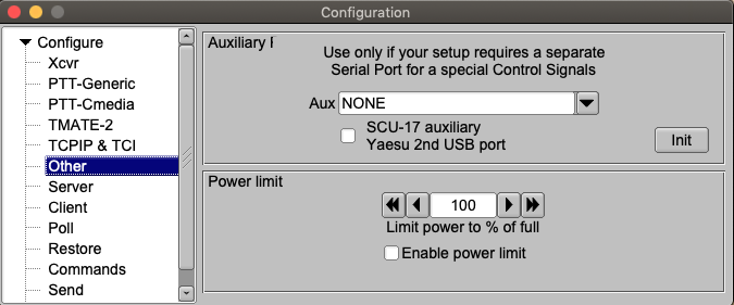
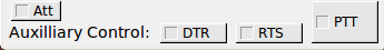
You might also need access to special h/w functions. FLRIG provides this via the DTR and RTS signal lines of an independent serial port. Additional main dialog controls are enabled and shown if you select anything other than NONE (the default). Enable the "Serial Port is SCU-17 auxiliary" if you are using the SCU-17 secondary serial port.
Also on this same page a transmit power out limit may be set if your radio supports that feature. To activate it just set the desired power level and check the enable box.
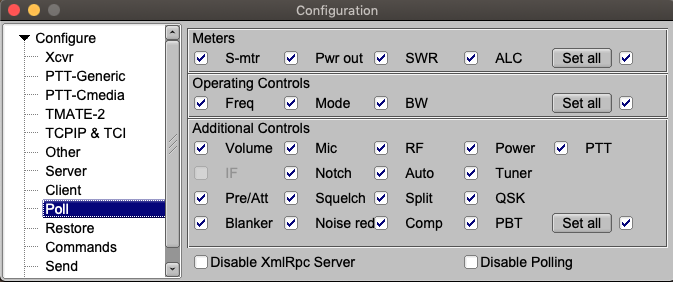
Providing your transceiver supports the various meters and controls, you can elect to poll these every time the poll cycle occurs. Polling a value causes FLRIG to follow as well as control a particular transceiver function or control. The polling cycle will slow down as you elect to poll more and more values.
Configuration and data files used by flrig consist of the following:
| OS | Folder | File | Usage |
|---|---|---|---|
| Windows XP | c:\Documents and Settings\user-name\flrig.files | flrig.prefs | names transceiver file & xmlrpc port |
| Windows XP | c:\Documents and Settings\user-name\flrig.files | IC-7100.prefs (1)(2) | IC-7100 specifc configuration items |
| Windows XP | c:\Documents and Settings\user-name\flrig.files | IC-7100.mat (1)(2) | IC-7100 specific memory file |
| Windows 7/8/10 | c:\Users\user-name\flrig.files | flrig.prefs | names transceiver file & xmlrpc port |
| Windows 7/8/10 | c:\Users\user-name\flrig.files | IC-7100.prefs (1)(2) | names transceiver file & xmlrpc port |
| Windows 7/8/10 | c:\Users\user-name\flrig.files | IC-7100.mat (1)(2) | names transceiver file & xmlrpc port |
| Linux/Unix/OS-X | $HOME/.flrig | flrig.prefs | names transceiver file & xmlrpc port |
| Linux/Unix/OS-X | $HOME/.flrig | IC-7100.prefs (1)(2) | names transceiver file & xmlrpc port |
| Linux/Unix/OS-X | $HOME/.flrig | IC-7100.mat (1)(2) | names transceiver file & xmlrpc port |
(1) Several TRANSCEIVER.prefs and mat files may be in the folder. Each specifc to the configured transceiver
(2) Files such as IC-7100.prefs.1, IC-7100.mat.1, up to a prefix of 5 may appear in the folder. These are aged files, with the oldest file having the largest prefix value. The mat files are only created if the user actually saved items to memory.
Transceiver Prefs details are shown in this file: Prefs file contents.
The file is human readable. Editing the file is not recommended.