Some analog transmissions such as FAX, MFSK images, and Thor images will exhibit a slant in the received image if the sound card clock (sample rate) is not identical at both the transmitter and receiver. The best way to insure that they are identical is to calibrate both to an external frequency and time standard. Operators in the North American region can use the WWV and/or WWVH standard time transmissions for this purpose. European and Asian users should be able to use the German DCF-77 or Russian RMW time transmissions.
The WWV mode is used to measure the offset of the sound card oscillator. It does this by comparing the sound card sample rate with the clock tick signal that is transmitted by WWV and WWVH.
The sampling rate for the sound card should be set to "native". The sound card samples the signal and returns a block of samples in blocks of 512. This block sampling is what sets the basic timing mechanism for the thread that reads the sound card. Most modern soundcards will use 44100 or 48000 as the native smampling rate. The sampled signal is filtered and reduced to a sample rate of 1000 by a process called decimiation in time. The resulting signal is then power detected and low pass filtered with a filter called a moving average filter. The moving average is very good at detecting the edge of a pulse such as the 1 second tick transmitted by WWV.
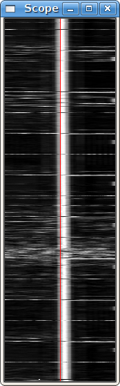
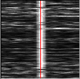
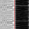
This decoded/filtered signal is then displayed in a manner very similar to a FAX signal. Each scan line represents the received signal over a 1 second interval. The bright white line is the time tick. You can see a very slight slope from left to right as the signal goes from top to bottom of the display.
Open the configure dialog box to the "SndCrd" tab. You are going to be adjusting the "Rx PPM" while you observe the effect of this control on the slope of the time tick line.
Tune in WWV or WWVH on 2.5, 5.0, 10.0 or 15.0 MHz in the AM mode. This seems to give the best signal view. Select the WWV modem. Open the scope dialog from the menu "View / Floating scope". Adjust the scope dialogs width and height to a 1:3 or greater ratio. Signal data will begin to accumulate in the digiscope display.
When you can clearly see the bright tick line, move the cursor to the bottom of the line and left click at that position. That will resync the digiscope display and put the ensuing tick marks at the center line red graticule. Then right click anywhere in the digiscope display. That changes the zoom level to show more signal detail and the slope of the time tick line will be more discernable. The zoom level increases by a factor of 5. Right clicking again restores the original zoom level. I recommend making the adjustments to the Rx PPM control in the x5 zoom level.
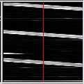
If the slope of the time tick line is positive you will need to apply a negative value to the Rx PPM. If it is negative then a positive correction is needed.
Start with a correction of 0 ppm and observe the slope. Try a value of 1000 ppm and observe the slope. Again, try a -1000 ppm correction and observe the slope. The following are some observations made on 10 MHz WWV, DCF-77 and RWM under less than ideal conditions.
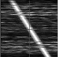
-1000 ppm WWV 5x scale |
0 ppm WWV 5x scale |
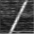
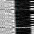
+1000 ppm WWV 5x scale |
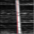
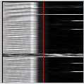
 +120 ppm WWV
5x scale |
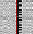
0 ppm DCF-77 1x scale |
0 ppm DCF-77 5x scale |
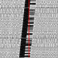
+1000 ppm DCF-77 1x scale |
+65 ppm DCF-77 5x scale |
RWM uncorrected 1x scale |
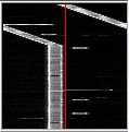
RWM +25361 ppm 1x scale |
RWM +25361 ppm 5x scale |
|
You can see that my sound card requires a positive correction since the slope is negative with a 0 ppm entry. The required correction of +120 ppm was determined by guessing the needed correction to be close to 1/10 of the -1000 ppm slope and then adjusting for a steady track along the red graticule. The DCF-77 images were provided by Walter, DL8FCL. The RWM images were provided by Andy G3TDJ.
You can left click on the tick line anytime you want to recenter the signal. That will aid in making your visual observation.
When you are finished, the Rx PPM entry is the correct one for your sound card. Save the configuration for future fldigi use.
Andy also provided information on the RWM transmissions:
RWM details extracted from http://www.irkutsk.com/radio/tis.htm
Station RWM - Main characteristics
Location: Russia, Moscow
55 degr. 44' North , 38 degr. 12' East
Standard frequencies : 4996, 9996 and 14996 kHz
Radiated power: 5kW on 4996 and 9996 kHz; 8kW on 14996 kHz
Period of operation: 24 hours per day, except 08.00-16.00 msk for maintenance as below:
on 4996 kHz : 1st wednesday of the 1st month of quater;
on 9996 kHz : 2nd wednesday of the 1st month of the quater;
on 14996 kHz : 3rd wednesday of each odd month;
Coverage: 20 degr. - 120 degr. East
35 degr. - 75 degr. North
Time signals A1X are given every second of 100 ms duration with a frequency of 1 Hz. Minute pip is extended to 500 ms.
Hourly transmission schedule
m:s - m:s
00:00 - 07:55 – MON signals (no modulation)
08:00 - 09:00 – transmitter is signed off
09:00 - 10:00 – station's identification is sent by Morse Code
10:00 - 19:55 – A1X signals and identification of DUT1+dUT1
20:00 - 29:55 – DXXXW signals
30:00 - 37:55 – N0N signals (no modulation)
38:00 - 39:00 – transmitter is signed off
39:00 - 40:00 – station's identification is sent by Morse Code
40:00 - 49:55 – A1X signals and identification of DUT1+dUT1
50:00 - 59:55 – DXXXW signals
See Transmitting Simulated WWV Timing Tone