Fldigi can be used to accurately measure the frequency of a remote signal that is transmitting a steady carrier, such as WWV or an ARRL sponsored Frequency Measurement Test signal.
The program can track and record two signals simultaneously. One can be the unknown remote signal: "Unk:". The second can be a local signal generated from a precision signal generator: "Ref:". If the reference signal is much more stable than the receiver, then drift and thermal effects observed on both the unknown and reference signals should be identical. Post measurement processing will allow the user to remove those from the unknown frequency.
The unknown and reference tracking points are selected using
- waterfall cursor: SHIFT left mouse click for unknown track
-
waterfall cursor: CONTROL left mouse click for reference track
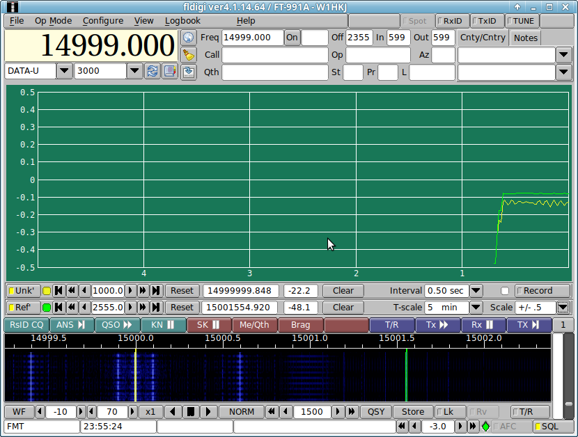
The screen shot shows the unknown (blue), reference (yellow), and cursor tracks (3 lines) on the waterfall. -
Fine tuning both is accomplished using the respective tracking controls:
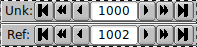
- Outer buttons: +/- 10. Hertz
- Middle butons: +/- 1.0 Hertz
- Inner buttons: +/- 0.1 Hertz
Each signal track is uniquely identified by color. The track color is displayed to the right of the frequency controls. The plot color and waterfall track bars are keyed to one another. The signal plots show error from the assigned tracking points.
Signal tracking for each can be turned on and off using the respective Unk / Ref button.
The averaged computed frequency is shown in the readout control. The averaged signal amplitude in dBvp is displayed to the right of the frequency.
Each track can be independently reset. Each track plot can be independently cleared.
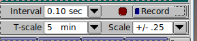
The controls "Interval", "T-scale", "Scale", and the button "Record" are common to both tracked signals.
- Interval: select the time interval between records in the data character separated value file (format shown below).
- T-scale: select the number of minutes displayed in the plot panel. This control will not effect the data history, only it's visibility.
- Scale: select the vertical scale of the plot panel. This control does not effect the actual data, only it's display.
- Record: toggle the csv recording on / off. Each new ON starts a new file that is date-time stamped to the nearest minute. Filename aging is applied to the filename if more than a single on/off event occurs within the same minute. Either or both Unknown and Reference "Track" must be enabled for any recording to take place.
Recording will synchronize the data lines with UTC. Synchronization should occur within a second. The indicator to the left of the recording button will change from white to dark red when data recording has begun.
The recording files are saved in the folder ~/.fldigi/fmt; C:\User\<login>\fldigi.files\fmt\
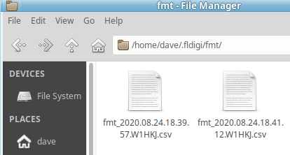
Example of recorded csv file opened using LibreCalc:
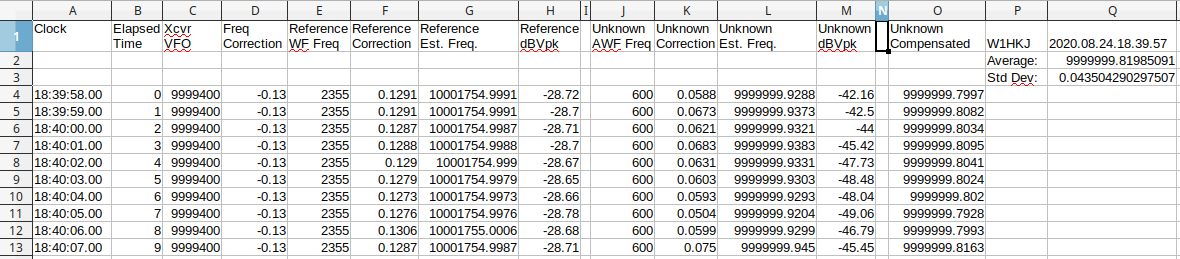
- Recorded file format as shown . Recording is not initiated by waterfall selections as occurs in the analysis modem.
- Reference Est. Freq. is computed as the sum of cells C, D, E and F on the same row
- Unknown Est. Freq. is computed as the sum of cells C, D, J and K on the same row.
- Unknown Compensated is computed as the difference of cells L and F on the same row.
- The average entry is computed: average(O:O)
- The standard deviation entry is computed: stdev(O:O)
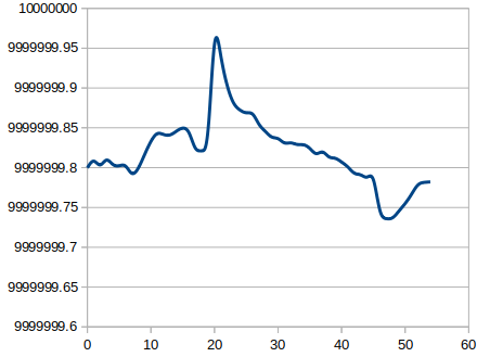
A plot of the elapsed time versus unknown frequency produced:
If a reference signal is not available, the user should just track the unknown. The resulting spreadsheet:
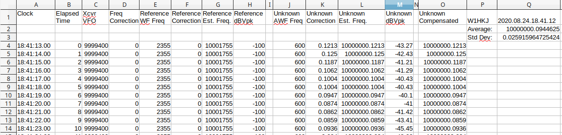
will have the reference columns set to NIL values. The final Unknown Compensated, Average, and Standard Deviation computations will be correct for the singular tracked signal.
FMT configuration
Right click the left most control on the status line FMT to open the configuration dialog to the FMT settings panel:
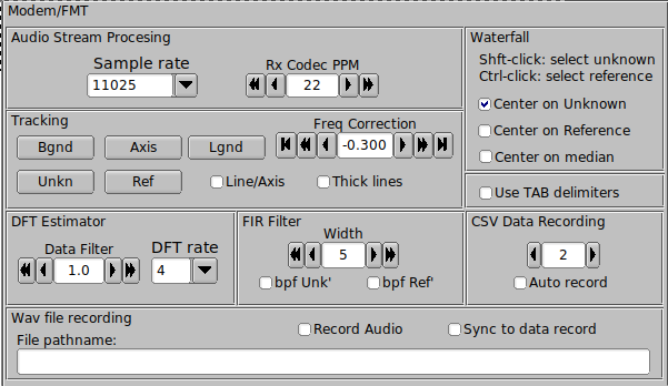
Adjust the various colors to suit your visual acuity. The decoder converts the tracked signals to base band, much like a direct conversion receiver might do.
Enable "Thick plot lines" for a bolder plot grid and data lines.
Enable "Line/Axis" if you want the data plot to overlie the horizontal axis.
Audio Stream Processing
- Rx Codec PPM You may already have used the WWV time tick modem to compensate for the audio codec (sound card) master oscillator error. The Rx Codec PPM control mirrors the control on the sound card panel. Audio codec compensation insures that the frequency measurement will be correct over the received audio bandwidth. This is discussed further under audio code sample rate errors.
-
Sample rate The decoder can be set to a number of sample rates.
Suggest using 1/4 the native sample rate of the audio codec. For most transceiver built-in audio codecs the rate will be 44100, use 11025.
Transceiver frequency correction
-
Freq Correction Your receiver may not be adjustable to less than 1 Hz.
The Rx Offset adds a fine tuning adjustment to both tracked signals. Changes to this control will result in moving the track lines up or down. It does not physically change the transceiver tuning. This control can be adjusted in 1, 10 and 100 millihertz increments.
Waterfall
-
fldigi waterfall controls include a x1, x2 and x4 scale. When changing between scales the program will try to always center at the current signal tracking point. Select whether that will be at
- the unknown signal track
- the reference signal track
- the median point between the two tracks, or the default of 1500 Hz (no selection)
Tab delimiters
-
The recorded data file uses a text format known as character separated values, csv. The default separator character is a comma. CSV is often called comma separated values. Issues arise when the value fields also contain commas.
For some locale's (European), the comma is the decimal value rather than a period.
fldigi attempts to reduce confusion between the decimal and character separators by quoting all values, i.e. enclose every value in quotations, "". Unfortunately s ome spread sheet programs still fail to properly load the data correctly into a spreadsheet. The solution is to use another separator character, the TAB.
Enable TAB separators if your locale uses the comma for decimal separation.
DFT Estimator
- Data Filter This is a post discriminator filter implemented as a sliding average filter. The average is computed over the last 'n' selected seconds.
- DFT rate Number of discriminator estimates made per second. The estimate is always over the last 1 second of audio stream data. The one per second rate is always an unbiased estimate. Faster rates are a sliding window over the past second, and each estimate computation is not independent of past estimates.
- FIR band pass filter Both unknown and reference signals can be passed through a band pass filter implemented as a Finite Impulse Response filter. The filter precedes the discriminator processing. The filter width can be set from 50 to 400 Hertz in 50 Hertz increments. Each filter can be independently enabled.
-
DFT controls
- Hard limiter - the Discrete Fourier Transform estimator computes the difference between the current and measured signal frequencies. That difference is then applied to the current estimate. If enabled the hard limiter constrains that difference to +/- the assigned limit value.
-
Cull - If enabled, difference values greater than the cull level are set to zero.
This is a live data recording showing the effectiveness of culling. The track later t han minute 12 was without culling. The track from 0 to 12 was with cull on at level 0.050. During the brief interval with almost no noise the cull level was set to 0.005.
You can cull the estimator to oblivion.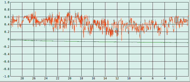
Wave file recording
- Record Audio - turn on and off wav file recording. wav file is located in same fmt folder as data recordings. New file is opened with a date-time stamped file name each time this function is enabled. Current recording file name is displayed in the context control. When enabled the "Sync to record" is deactivated.
-
Sync to record - wav file recording turns on/off in sync with the data record button.
wav file and csv file will have identical date-time stamped filenames, one with a .csv and the other a .wav file name extension. When enabled the "Record Audio" is deactivated.
Audio Codec sample rate errors
A sample rate clock error measurable in parts per million, ppm, is a factor that needs to be considered for several modems, including FMT. The error is visible when receiving an MFSK, IFKP or THOR image. The error shows up as a slant in the received image. For images it is usually the differential ppm between the sending and receiving codec.
On FMT measurements, the ppm error effects the error across the receiver passband.
Owners of a GPSDO can verify my measurement. The transceiver is fixed at a known frequency; for the test it was 5.003.000 Hz. The GPSDO is then slowly stepped from 5.003.400 to 5.005.800 Hz.
At each step the tracking error is measured. The absolute error is interesting but not relevant to this measurement. We are interested in the stability of the error across the passband. Here are my results for three ppm settings, 0, +10, a nd +20 for the FT991A / transceiver internal codec. The WWV time tick adjustment for ppm results in +10 ppm.
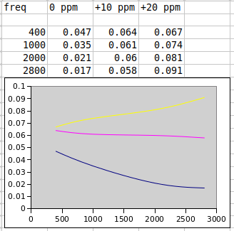
The WWV time tick ppm measurement and the passband error correlate almost exactly.
This tells me that I can compensate for the audio tracking points for any calibrated ppm setting, preferably the one that results in a zero error slope across the pass band.
Return to Top of Page
Return to Main Page