Table of Contents
BPSK, QPSK, 8PSK modems
PSK are narrow band low to moderate symbol rate modes using either single or multiple carrier differential Phase Shift Keying.
Current supported variants:
BPSK: Binary, 2 constellations (1)
QPSK: Quadrature, 4 constellations
8PSK: Octal, 8 constellations
- (1)
- A convenient way to represent PSK schemes is on a constellation diagram. This shows the points in the complex plane where, in this context, the real and imaginary axes are termed the in-phase and quadrature axes respectively due to their 90° separation.
- NOTE:
- Multi-Channel PSK modems use BPSK modulation.
PSK63FEC and the PSKxxxR modes are forward error correcting modes. PSK63FEC is compatible with the MultiPsk mode of the same name. The PSKxxxR, or robust, modes use both forward error correction and interleaving to achieve about 4 dB s/n improvement over standard PSK. These modes are used primarily by the PskMail user community. They are the invention of John Douyere, VK2ETA, a member of the fldigi development team.
In addition to the binary phase shift keying the signal is 100% raised-cosine amplitude modulated at the symbol rate. This reduces the power to zero at the phase change. Because of this amplitude modulation, the signal bandwidth is relatively narrow. Synchronization at the receiver is straight forward because it can be recovered from the amplitude information. Differential PSK is used to provide continuous phase changes when idle (to maintain sync), and by allowing the receiver to measure phase difference from symbol to symbol, to reduce the effects of ionospheric Doppler phase changes which modulate the signal. The slower modes are more affected by Doppler, and the QPSK and 8PSK modes are particularly affected.
With no interleaver and limited coding length, the QPSK mode Forward Error Correction coding gain is limited, and under burst noise conditions on HF the performance is usually worse than the BPSK option at the same baud rate. In general the narrow-band BPSK modes work well on a quiet single-hop path, but give poor performance in most other conditions.
Many of the multi-carrier and 8PSK modes exceed the baud and bandwidth limitations imposed by the FCC (US operators only). These modes are intended for use on VHF/UHF and have proven to be very robust on FM even when used with repeaters.

Multi-Channel BPSK modems
8PSK modems
The 8 PSK modes are intended for use on VHF/UHF FM systems. They provide a very high data rate suitable for use with both flmsg and flamp and the transfer of digital data.
FM Modes - There are five modes specifically intended for usage on FM:
| Mode | WPM | Baud | Bitrate | Datarate | FEC |
|---|---|---|---|---|---|
| 8-PSK 500 | 2540 | 500 | 1500 bps | 1500 bps | None |
| 8-PSK 1000 | 5080 | 1000 | 3000 bps | 3000 bps | None |
| 8-PSK 500F | 1690 | 500 | 1500 bps | 1000 bps | 2/3 Rate K=13 |
| 8-PSK 1000F | 3386 | 1000 | 3000 bps | 2000 bps | 2/3 Rate K=7 |
| 8-PSK 1200F | 4170 | 1200 | 3600 bps | 2400 bps | 2/3 Rate K=7 |
- 8-PSK 500F works with nearly all radios and FM repeater systems.
- Center-frequencies of 1500Hz and 1750Hz have been reported to work best.
SSB Modes - There are six modes which can be used for weak signal 10m/6m+ SSB or FM VHF/UHF.
| Mode | WPM | Baud | Bitrate | Datarate | FEC |
|---|---|---|---|---|---|
| 8-PSK 125 | 635 | 125 | 375 bps | 375 bps | None |
| 8-PSK 250 | 1270 | 250 | 750 bps | 750 bps | None |
| 8-PSK 125F | 317 | 125 | 375 bps | 187 bps | 1/2 Rate K=16 |
| 8-PSK 250F | 635 | 250 | 750 bps | 375 bps | 1/2 Rate K=16 |
| 8-PSK 125FL | 312 | 125 | 375 bps | 187 bps | 1/2 Rate K=13 |
| 8-PSK 250FL | 635 | 250 | 750 bps | 375 bps | 1/2 Rate K=13 |
| 8-PSK 500F | 1690 | 500 | 1500 bps | 1000 bps | 2/3 Rate K=13 |
These modes can be used on HF SSB like PSK-31, but do require a high-degree of frequency accuracy ( ± 10Hz ).
The heavy forward error correction allows these signals to be decoded even when quite weak. This also helps overcome their sensitivity to transmitter / amplifier distortions and non-linearities.
The FEC modes do not all use the same Viterbi polynomials to achieve the forward error correction. That is why the WPM rates for the FEC modes are not multiples of the base 125 baud. The WPM rates are only an indication of relative rates.
The actual transfer rate is highly dependent on the data content. This is always true for modes which use a VARICODE.
The 8psk signal is similar to both bpsk and qpsk, but with 8 possible phase states instead of the 2 and 4 associated with bpsk, qpsk. The format of the signal does not lend itself easily to a conventional AFC. Instead, the modes should be used with RsID enabled. The RsID signal will both determine the mode and the mode center frequency (to the nearest 2.6 Hz). A finer resolution of the mode center frequency can be made using the optional pilot carrier. This pilot carrier is placed at the frequency
f0 – samplerate / symbollen, f0 is modem center frequency
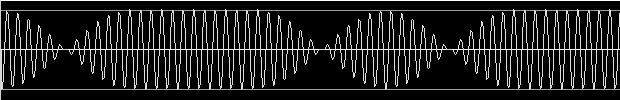
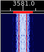
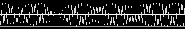
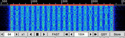
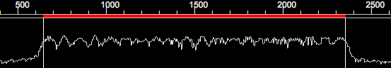
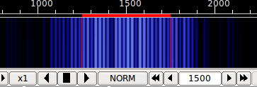
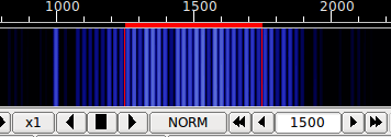
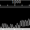
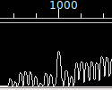
samplerate / symbollen is the same as the mode bandwidth. The waterfall and spectrum signature for the 8psk500 mode is shown here with and without the pilot carrier:
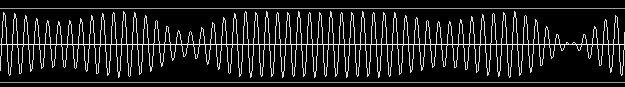

The two oscilloscope views above clearly show the combined phase and amplitude modulation of these modes.
Decoding errors are reduced as the tracking point nears the actual transmit center frequency. The loss of signal power is more than offset by the decoder improvement.
Field testing has shown that the pilot tone needs to be at -40 dB or greater (less negative).
The 8-PSK pilot carrier is a continuous-phase & continuous-frequency tone transmitted slightly lower in frequency than the 8-PSK data signal. Since 8-PSK cannot use the same auto-frequency controls (AFC) as BPSK or PSK31 can, this tone is used to provide a frequency/phase reference.
The addition of a pilot carrier to the 8-PSK modes allows for expanded usage of 8-PSK over HF Single-Sideband, even with older radios that experience frequency drift. This carrier helps improve decode by:
- Compensating for frequency drift, common with older radios
- Providing a stable frequency reference with +- 1/2 Hz accuracy
- Providing information on the RF channel quality, by measuring the RF channel real-time
Pilot tone detection does require a bit more cpu power. The pilot tone is detected using a sliding fast Fourier transform, sfft, which computes the frequency of the pilot to approximately 1 Hz resolution. The sfft only evaluates the signal at 11 discrete frequencies, so it is necessary that either the RsID, or manual tuning is used for the initial signal acquisition. The detector is set to provide lock when the pilot s/n is 2:1 or better. The signal tracking point is then adjusted to place the pilot tone at the correct frequency location. For example, if the RsID put the tracking point at 1502 Hz, the pilot would then adjust for 1500 (if that is the correct tracking frequency). The adjustment is made once per second. Unlike AFC, which is continuous, the pilot adjustment is discrete and occurs in 1 Hz steps. If the pilot s/n is less than 2:1 then no adjustment is made to the tracking point. The pilot tone is transmitted during the 8psk preamble as well as during the data transmission. You should see the tracking point adjust once at the beginning of the transmission and then stay fixed.
With these modes, a very linear transmitter is required. Over-driven operation results in excessive bandwidth, poorer reception and difficult tuning. Overdrive usually occurs by having the audio signal much too large. These are very sensitive modes and usually very little power is required. QRP operation of 80, 40, 30 and 20 meters can provide nearly 100% copy over multi-hop paths. In many instances PSK can provide better decoding than CW.
Setting up for a good clean on air signal that will receive the accolades of your QSO partners is easy. Follow the instructions on using the Tune button and you will have a clean on signal.
Good reception of PSK signals requires that the demodulator be phase locked to the incoming signal. Fldigi has both a fast acquire / slow tracking AFC system. Place the red bandwidth bar (see above) so that it overlies the desired signal and then press the left mouse button. The signal should quickly lock on a decoding should commence immediately. It is almost impossible to visually tell whether a BPSK or QPSK signal is being received. Under very high s/n you might be able to hear the difference, but that is even difficult for most operators. If you are not able to decode a signal that looks like a BPSK and the bandwidth of the signal matches the baud rate then it might be a QPSK signal. Just change mode a try reacquiring the signal.
For further information about Phase Shift Keying