Table of Contents
This document describes the contents of the rig definition file "rig.xml".
A number of transceivers have rig definition files written and tested which you may use. These are found in the xmls directory on this site: xml archives. You will find subdirectories by manufacturer which contain files named by rig type, ie: TS-850.xml. If you create, test and verify the proper operation for a transceiver not yet posted please share that with others by sending it as an attachment to feedback [at] w1hkj [dot] com and I will post it on the web site. You are encouraged to study the various rig definition files to learn more about how they are organized.
Comments are contained within the tag pair:
<!--
...
-->
and may appear anywhere in the rig definition file The entire rig definition must be contained within the tag pair
<RIGDEF>
...
</RIGDEF>
The text within the tag pair <RIG></RIG> specifies the transceiver to which this file applies, as in:
<RIG>Icom 746 PRO</RIG>
The text within the tag pair <PROGRAMMER></PROGRAMMER> is not used by the parser, but should as a minimum say who created and who tested the definition file, as in:
<PROGRAMMER>
    Dave Freese W1HKJ Tested by: W1HKJ, Dave
</PROGRAMMER>
The text within the tag pair
<STATUS> ... </STATUS>
is not used by the parser, but should as a minimum state whether the definition file has been "Verified", is "Alpha&", what the Version and Date of creation or update, as in:
<STATUS> Verified Version: 1.0 Date: 2007 Jan 5 </STATUS>
The title bar tag pair contains the text which will be displayed on the window decoration bar, as in:
<TITLE>Rig Control - IC-746 PRO</TITLE>
Serial Port Parameters
The serial port parameters may be preset in the xml file and also set or changed on the rigCAT configuration tab. These values are loaded from the xml file. If a value is changed on the configuration tab it is saved in the progdefaults.xml file if the configuration is saved. On a subsequent start of fldigi the saved parameters will override the ones in the rig definition file.
| xml tag | parameter | description |
| <TIMEOUT>TT</TIMEOUT> | TT in milliseconds | serial port timeout |
| <RETRIES>NN</RETRIES> | NN integer | number of times CAT string is resent |
| <WRITE_DELAY>TT</WRITE_DELAY> | TT in milliseconds | wait time after sending normal command to xcvr |
| <INIT_DELAY>IT</INIT_DELAY> | IT in milliseconds | wait time after sending init string to xcvr |
| <BAUDRATE>BAUD</BAUDRATE> | BAUD integer | 1200, 2400, 4800, 9600, 19200, 38400 ... |
| <STOPBITS>B</STOPBITS> | B integer | 1 or 2 |
| <RTSCTS>BOOL</RTSCTS> | BOOL true, false | h/w handshake used for data flow control |
| <RTSPLUS>BOOL</RTSPLUS> | BOOL true, false | set RTS signal line to +12 V (default -12 V) |
| <RTSPTT>BOOL</RTSPTT> | BOOL true, false | toggle RTS signal line for PTT |
| <DTRPLUS>BOOL</DTRPLUS> | BOOL true, false | set DTR signal line to + 12 V (default -12 V) |
| <DTRPTT>BOOL</DTRPTT> | BOOL true, false | toggle DTR signal line for PTT |
| <CMDPTT>BOOL</CMDPTT> | BOOL true, false | use command string for PTT (not supported by all xcvrs) |
| <ECHO>BOOL</ECHO> | BOOL true, false | xcvr/interface echoes all chars (typical of CI-V interface) |
| <WAIT_FOR_DEVICE>nnn</WAIT_FOR_DEVICE> | nnnn in milliseconds | used for correct startup of K9MJ CI-V router |
| <VSP>BOOL</VSP> | BOOL true/false | serial port is a virtual device |
Poll Interval
The rigCAT code operates in a separate thread during which the various queries are made with a default interval of 100 milliseconds between the last query and the start of the next cycle. The actual cycle period is dependent on the serial communications baud rate, the size of the commands, and the responsiveness of the transceiver. It will always be greater than the poll interval.
You can specify a poll interval in milliseconds in the xml file:
<POLLINT>mmm</POLLINT>
where mmm is the poll interval in milliseconds.
Modes
The transceiver modes are specified within the <MODES></MODES> tag pair. Each entry or element associated with a mode has a symbol name (text) and a way to specify what the data transfer consists of. The data transfer might be a single byte, multiple bytes, or a string
Example 1, for the Icom-746PRO
<MODES>
  <ELEMENT><SYMBOL>LSB</SYMBOL><BYTE>00</BYTE></ELEMENT>
  <ELEMENT><SYMBOL>USB</SYMBOL><BYTE>01</BYTE></ELEMENT>
  <ELEMENT><SYMBOL>AM</SYMBOL><BYTE>02</BYTE></ELEMENT>
  <ELEMENT><SYMBOL>CW</SYMBOL><BYTE>03</BYTE></ELEMENT>
  <ELEMENT><SYMBOL>RTTY</SYMBOL><BYTE>04</BYTE></ELEMENT>
  <ELEMENT><SYMBOL>FM</SYMBOL><BYTE>05</BYTE></ELEMENT>
  <ELEMENT><SYMBOL>CW-R</SYMBOL><BYTE>07</BYTE></ELEMENT>
  <ELEMENT><SYMBOL>RTTY-R</SYMBOL><BYTE>08</BYTE></ELEMENT>
</MODES>
Example 2, for the Kenwood 850
<MODES\>
  <ELEMENT><SYMBOL>LSB</SYMBOL><BYTE>31</BYTE></ELEMENT>
  <ELEMENT><SYMBOL>USB</SYMBOL><BYTE>32</BYTE></ELEMENT>
  <ELEMENT><SYMBOL>CW</SYMBOL><BYTE>33</BYTE></ELEMENT>
  <ELEMENT><SYMBOL>FM</SYMBOL><BYTE>34</BYTE></ELEMENT>
  <ELEMENT><SYMBOL>AM</SYMBOL><BYTE>35</BYTE></ELEMENT>
  <ELEMENT><SYMBOL>FSK</SYMBOL><BYTE>36</BYTE></ELEMENT>
  <ELEMENT><SYMBOL>CW-R</SYMBOL><BYTE>37</BYTE></ELEMENT>
  <ELEMENT><SYMBOL>FSK-R</SYMBOL><BYTE>39</BYTE></ELEMENT>
</MODES>
Example 3, for the FT-100
<MODES>
  <ELEMENT><SYMBOL>LSB</SYMBOL><BYTE>00</BYTE></ELEMENT>
  <ELEMENT><SYMBOL>USB</SYMBOL><BYTE>01</BYTE></ELEMENT>
  <ELEMENT><SYMBOL>CW</SYMBOL><BYTE>02</BYTE></ELEMENT>
  <ELEMENT><SYMBOL>CW-R</SYMBOL><BYTE>03</BYTE></ELEMENT>
  <ELEMENT><SYMBOL>AM</SYMBOL><BYTE>04</BYTE></ELEMENT>
  <ELEMENT><SYMBOL>DIG</SYMBOL><BYTE>05</BYTE></ELEMENT>
  <ELEMENT><SYMBOL>FM</SYMBOL><BYTE>06</BYTE></ELEMENT>
  <ELEMENT><SYMBOL>W-FM</SYMBOL><BYTE>07</BYTE></ELEMENT>
</MODES>
The modes which are supported by lower sideband in the transceiver are specified in the <LSBMODES></LSBMODES> tag pair. The string data for the LSB modes must match those given in the modes id specifier For example in the Icom 746 Pro:
<LSBMODES>
  <STRING>LSB<STRING>
  <STRING>RTTY<STRING>
  <STRING>CW-R<STRING>
</LSBMODES>
Bandwidth Specifier
If the transceiver data stream uses identically the same format for the bandwidth data then it is specified in the <BANDWIDTHS></BANDWIDTHS> tag pair
Example for the Icom 746 Pro:
<BANDWIDTHS>
  <ELEMENT><SYMBOL>50</SYMBOL><BYTE>00</BYTE></ELEMENT>
  <ELEMENT><SYMBOL>100</SYMBOL><BYTE>01</BYTE></ELEMENT>
  <ELEMENT><SYMBOL>150</SYMBOL><BYTE>02</BYTE></ELEMENT>
  <ELEMENT><SYMBOL>200</SYMBOL><BYTE>03</BYTE></ELEMENT>
  <ELEMENT><SYMBOL>250</SYMBOL><BYTE>04</BYTE></ELEMENT>
  <ELEMENT><SYMBOL>300</SYMBOL><BYTE>05</BYTE></ELEMENT>
  <ELEMENT><SYMBOL>350</SYMBOL><BYTE>06</BYTE></ELEMENT>
  <ELEMENT><SYMBOL>400</SYMBOL><BYTE>07</BYTE></ELEMENT>
  <ELEMENT><SYMBOL>450</SYMBOL><BYTE>08</BYTE></ELEMENT>
  <ELEMENT><SYMBOL>500</SYMBOL><BYTE>09</BYTE></ELEMENT>
  <ELEMENT><SYMBOL>600</SYMBOL><BYTE>10</BYTE></ELEMENT>
  <ELEMENT><SYMBOL>700</SYMBOL><BYTE>11</BYTE></ELEMENT>
  <ELEMENT><SYMBOL>800</SYMBOL><BYTE>12</BYTE></ELEMENT>
  <ELEMENT><SYMBOL>900</SYMBOL><BYTE>13</BYTE></ELEMENT>
  <ELEMENT><SYMBOL>1000</SYMBOL><BYTE>14</BYTE></ELEMENT>
  <ELEMENT><SYMBOL>1100</SYMBOL><BYTE>15</BYTE></ELEMENT>
  <ELEMENT><SYMBOL>1200</SYMBOL><BYTE>16</BYTE></ELEMENT>
  <ELEMENT><SYMBOL>1300</SYMBOL><BYTE>17</BYTE></ELEMENT>
  <ELEMENT><SYMBOL>1400</SYMBOL><BYTE>18</BYTE></ELEMENT>
  <ELEMENT><SYMBOL>1500</SYMBOL><BYTE>19</BYTE></ELEMENT>
  <ELEMENT><SYMBOL>1600</SYMBOL><BYTE>20</BYTE></ELEMENT>
  <ELEMENT><SYMBOL>1700</SYMBOL><BYTE>21</BYTE></ELEMENT>
  <ELEMENT><SYMBOL>1800</SYMBOL><BYTE>22</BYTE></ELEMENT>
  <ELEMENT><SYMBOL>1900</SYMBOL><BYTE>23</BYTE></ELEMENT>
  <ELEMENT><SYMBOL>2000</SYMBOL><BYTE>24</BYTE></ELEMENT>
  <ELEMENT><SYMBOL>2100</SYMBOL><BYTE>25</BYTE></ELEMENT>
  <ELEMENT><SYMBOL>2200</SYMBOL><BYTE>26</BYTE></ELEMENT>
  <ELEMENT><SYMBOL>2300</SYMBOL><BYTE>27</BYTE></ELEMENT>
  <ELEMENT><SYMBOL2400</SYMBOL><BYTE>28</BYTE></ELEMENT>
  <ELEMENT><SYMBOL>2500</SYMBOL><BYTE>29</BYTE></ELEMENT>
  <ELEMENT><SYMBOL>2600</SYMBOL><BYTE>30</BYTE></ELEMENT>
  <ELEMENT><SYMBOL>2700</SYMBOL><BYTE>31</BYTE></ELEMENT>
  <ELEMENT><SYMBOL>2800</SYMBOL><BYTE>32</BYTE></ELEMENT>
  <ELEMENT><SYMBOL>2900</SYMBOL><BYTE>33</BYTE></ELEMENT>
  <ELEMENT><SYMBOL>3000</SYMBOL><BYTE>34</BYTE></ELEMENT>
  <ELEMENT><SYMBOL>3100</SYMBOL><BYTE>35</BYTE></ELEMENT>
  <ELEMENT><SYMBOL>3200</SYMBOL><BYTE>36</BYTE></ELEMENT>
  <ELEMENT><SYMBOL>3300</SYMBOL><BYTE>37</BYTE></ELEMENT>
  <ELEMENT><SYMBOL>3400</SYMBOL><BYTE>38</BYTE></ELEMENT>
  <ELEMENT><SYMBOL>3500</SYMBOL><BYTE>39</BYTE></ELEMENT>
  <ELEMENT><SYMBOL>3600</SYMBOL><BYTE>40</BYTE></ELEMENT>
</BANDWIDTHS>
If the bandwidth data stream is unique for send and receive data streams then they are specified separately with a <BW-CMD></BW-CMD> tag pair for data sent to the transceiver, and a <BW-REPLY></BW-REPLY> tag pair for data returned to the computer. The number and symbol name for these must match.
Example: FT-100:
<BW-CMD>
  <ELEMENT><SYMBOL>300</SYMBOL><BYTE>00</BYTE></ELEMENT>
  <ELEMENT><SYMBOL>500</SYMBOL><BYTE>01</BYTE></ELEMENT>
  <ELEMENT><SYMBOL>2400</SYMBOL><BYTE>02</BYTE></ELEMENT>
  <ELEMENT><SYMBOL>6000</SYMBOL><BYTE>03</BYTE></ELEMENT>
</BW-CMD>

<BW-REPLY>
  <ELEMENT><SYMBOL>300</SYMBOL><BYTE>03</BYTE></ELEMENT>
  <ELEMENT><SYMBOL>500</SYMBOL><BYTE>02</BYTE></ELEMENT>
  <ELEMENT><SYMBOL>2400</SYMBOL><BYTE>01</BYTE></ELEMENT>
  <ELEMENT><SYMBOL>6000</SYMBOL><BYTE>00</BYTE></ELEMENT>
</BW-REPLY>
Commands and Replies
CAT command strings are defined within a <COMMAND>...</COMMAND> block. Each block structure appears as:
<COMMAND>
  <SYMBOL>...</SYMBOL>   noun name of symbol
  <SIZE>...</SIZE>       number of bytes in CAT string
  <STRING>...</STRING>   string literal (optional)
  <DATA>                 data block (optional)
    <DTYPE>...</DTYPE>   type of data in data block
    <SIZE>...</SIZE>     number of bytes in data block
    <MAX>...</MAX>       maximum value of data value
    <MIN>...</MIN>       minimum value of data value
    <RESOL>...</RESOL>   resolution of data value
  </DATA>                end of data block
  <STRING>...</STRING>   string literal (optional)
</COMMAND>
Here are three examples from the KX3.xml definition file
  <COMMAND>
    <SYMBOL>INIT</SYMBOL>
    <SIZE>12</SIZE>
    <STRING>AI0;DT0;K31;</STRING>
  </COMMAND>

  <COMMAND>
    <SYMBOL>SETFREQ</SYMBOL>
    <SIZE>14</SIZE>
    <STRING>FA</STRING>
    <DATA>
      <DTYPE>DECIMAL</DTYPE>
      <SIZE>11</SIZE>
      <MAX>99999999999</MAX>
      <MIN>00000490000</MIN>
      <RESOL>1</RESOL>
    </DATA>
    <STRING>;</STRING>
  </COMMAND>

  <COMMAND>
    <SYMBOL>GETFREQ</SYMBOL>
    <SIZE>3</SIZE>
    <STRING>FA;</STRING>
    <INFO>FREQ</INFO>
  </COMMAND>
A command string may have a corresponding reply string sent by the transceiver. The SYMBOL noun name for each command - reply pair is the same.
Fldigi can parse and decode message returned from the transceiver that define 4 aspects of the transceiver operation:
| OK | data accepted by the transceiver |
| BAD | data rejected by the transceiver |
| MODE | current operating mode of the transceiver |
| BW | current bandwidth setting of the transceiver |
| FREQ | frequency of the active VFO (might be either A or B for example) |
These are all contained within multiple <REPLY></REPLY> tag pairs. The REPLY block structure is:
<REPLY\>
  <SYMBOL>...</SYMBOL>         noun name of symbol
  <SIZE>...</SIZE>             number of bytes in reply string
  <BYTES>...</BYTES>           space separated hexadecimal values
  <BYTE>...</BYTE>             single hexadecimal value
  <STRING>...</STRING>         returned character string
</REPLY>
This is an example of a fixed format message with no variable fields. It is the OK message sent back by the Icom-746 PRO:
<REPLY>
  <SYMBOL>OK</SYMBOL>
  <SIZE>6</SIZE>
  <BYTES>FE FE E0 66</BYTES>
  <BYTE>FB</BYTE>
  <BYTE>FD</BYTE>
</REPLY>
The <SYMBOL></SYMBOL> pair and the command definition are mandatory. The <SIZE></SIZE> field is mandatory and specifies the number of bytes contained in this reply. The above definition could also have been coded as:
<REPLY>
  <SYMBOL>OK</SYMBOL>
  <SIZE>6</SIZE>
  <BYTES>FE FE E0 66 FB FD</BYTES>
</REPLY>
When the reply contains variable data it is specified in a contained tag pair <DATA></DATA>. This data field contains specifiers that describe the kind and size of the data. The <DTYPE></DTYPE> tag pair may be one of:
BINARY or
DECIMAL
This is an example for the reply to a mode query that is returned by the Icom-746 PRO:
<REPLY>
  <SYMBOL>MODE</SYMBOL>
  <SIZE>8</SIZE>
  <BYTES>FE FE E0 66</BYTES>
  <BYTE>04</BYTE>
  <DATA>
    <DTYPE>BINARY</DTYPE>
    <SIZE>1</SIZE>
   </DATA>
 <FILL>1</FILL>
 <BYTE>FD</BYTE>
</REPLY>
Fldigi rigCAT will check for both the preample and postamble to insure that a valid reply has been sent by the transceiver.
This is an example for the reply to a frequency query that is returned by the Elecraft KX3. The corresponding query command structure is shown above.
<REPLY>
  <SYMBOL>FREQ</SYMBOL>
  <SIZE>14</SIZE>
  <STRING>FA</STRING>
  <DATA>
    <DTYPE>DECIMAL</DTYPE>
    <SIZE>11\</SIZE>
    <MAX>99999999999</MAX>
    <MIN>00001500000</MIN>
    <RESOL>1</RESOL>
  </DATA>
  <STRING>;</STRING>
</REPLY>
Meters
fldigi rigCAT can query the transceiver for both Smeter and Power Meter. The fldigi user interface controls that display these values have a range of 0 to 100. You need to provide the scale conversion from queried value to fldigi UI control scale. The <SMETER>...</SMETER> and <PMETER>...</PMETER> are reserved pairs that are used to define the conversions. The program will interpolate between values as it converts the queried value to the user interface control range.
Here are two examples of scale specifiers:
<!-- smeter scale mapping for FT-950 -->
<SMETER> 0,0; 255,100 </SMETER>

<!-- power meter scale mapping for FT-950 -->
<PMETER>
  0,0; 16,1; 32,4; 48,7;
  64,12; 80,18; 96,24; 112,32;
  128,40; 144,50; 160,61; 176,73;
  192,85; 208,100
</PMETER>

<!-- smeter scale mapping for IC-706MkIIG -->
<SMETER> 0,0; 255,100 </SMETER>
The query and respective responses are coded as any other command/reply pair:
For the FT-950:
<REPLY>
  <SYMBOL>SMETER</SYMBOL>
  <SIZE>7</SIZE>
  <STRING>RM1</STRING>
  <DATA>
    <DTYPE>DECIMAL</DTYPE>
    <SIZE>3</SIZE>
  </DATA>
  <STRING>;</STRING>
</REPLY>

<COMMAND>
  <SYMBOL>GET_SMETER</SYMBOL>
  <SIZE>4</SIZE>
  <STRING>RM1;</STRING>
  <INFO>SMETER</INFO>
</COMMAND>

<REPLY>
  <SYMBOL>PWRMETER</SYMBOL>
  <SIZE>7</SIZE>
  <STRING>RM5</STRING>
  <DATA>
    <DTYPE>DECIMAL</DTYPE>
    <SIZE>3</SIZE>
  </DATA>
  <STRING>;</STRING>
</REPLY>

<COMMAND>
  <SYMBOL>GET_PWRMETER</SYMBOL>
  <SIZE>4</SIZE>
  <STRING>RM5;</STRING>
  <INFO>PWRMETER</INFO>
</COMMAND>
and for the IC-706MkIIG:
<REPLY>
    <SYMBOL>SMETER</SYMBOL>
    <SIZE>10</SIZE>
    <BYTES>FE FE E0 58 15 02</BYTES>
    <DATA>
        <DTYPE>BCD</DTYPE>
        <SIZE> 3 </SIZE>
        <MAX> 255 </MAX>
        <MIN> 0 </MIN>
        <RESOL> 1 </RESOL>
     </DATA>
    <BYTE>FD</BYTE>
</REPLY>

<COMMAND>
    <SYMBOL>GET SMETER</SYMBOL>
    <SIZE>7</SIZE>
    <BYTES>FE FE 58 E0 15 02 FD</BYTES>
    <INFO>SMETER</INFO>
</COMMAND>
Notch Control
The transceiver manual notch can be both read and controlled using rigCAT.
There are a few requirements that may not be met by all transceivers.
- it must support a CAT manual notch on/off string
- it must support a CAT manual notch value string
- the conversion between notch audio frequency and the CAT value must be bilateral.
Here is an example for the FT-950:
<NOTCH>
  1,10; 300,3000;
</NOTCH>

<COMMAND>
    <SYMBOL>SET_NOTCH_ON</SYMBOL>
    <SIZE>8</SIZE>
    <STRING>BP00001;</STRING>
</COMMAND>

<COMMAND>
    <SYMBOL>SET_NOTCH_OFF</SYMBOL>
    <SIZE>8</SIZE>
    <STRING>BP00000;</STRING>
</COMMAND>

<COMMAND>
    <SYMBOL>SET_NOTCH_VAL</SYMBOL>
    <SIZE>8</SIZE>
    <STRING>BP01</STRING>
    <DATA>
        <DTYPE>DECIMAL</DTYPE>
        <SIZE>3</SIZE>
    </DATA>
    <STRING>;</STRING>
</COMMAND>

<REPLY>
  <SYMBOL>NOTCH_ON</SYMBOL>
  <SIZE>8</SIZE>
  <STRING>BP00001;</STRING>
</REPLY>

<COMMAND>
  <SYMBOL>GET_NOTCH_ON</SYMBOL>
  <SIZE>5</SIZE>
  <STRING>BP00;</STRING>
  <INFO>NOTCH_ON</INFO>
</COMMAND>

<REPLY>
  <SYMBOL>NOTCH</SYMBOL>
  <SIZE>8</SIZE>
  <STRING>BP01</STRING>
  <DATA>
    <DTYPE>DECIMAL</DTYPE>
    <SIZE>3</SIZE>
  </DATA>
  <STRING>;</STRING>
</REPLY>

<COMMAND>
  <SYMBOL>GET_NOTCH</SYMBOL>
  <SIZE>5</SIZE>
  <STRING>BP01;</STRING>
  <INFO>NOTCH</INFO>
</COMMAND>
The notch is controlled from fldigi using the alt-ctl-left-click on the waterfall. The same keyboard-mouse combination is used to both set and clear the notch. Point the cursor to an offending signal, and then use the keyboard-mouse combination to set the manual notch at that frequency. Repeat the keyboard-mouse combination anywhere in the waterfall to clear the notch. The SET notch is indicated by a dashed vertical line on the waterfall display at the audio frequency being notched. You should also see a pronounced reduction in signal at that point. fldigi will also annunciate any transceiver changes made to the manual notch.
Power Level Control
rigCAT can control the power level of the transceiver if that is a supported CAT command. The definitions for the power level are similar to the notch in that the conversion should be bilateral.
Another example using the FT-950 transceiver:
<PWRLEVEL>
  0,0; 100,100;
</PWRLEVEL>

<REPLY>
  <SYMBOL>PWRLEVEL</SYMBOL>
  <SIZE>6</SIZE>
  <STRING>PC</STRING>
  <DATA>
    <DTYPE>DECIMAL</DTYPE>
    <SIZE>3</SIZE>
  </DATA>
  <STRING>;</STRING>
</REPLY>

<COMMAND>
  <SYMBOL>GET_PWRLEVEL</SYMBOL>
  <SIZE>3</SIZE>
  <STRING>PC;</STRING>
  <INFO>PWRLEVEL</INFO>
</COMMAND>

<COMMAND>
  <SYMBOL>SET_PWRLEVEL</SYMBOL>
    <SIZE>6</SIZE>
    <STRING>PC</STRING>
    <DATA>
        <DTYPE>DECIMAL</DTYPE>
        <SIZE>3</SIZE>
    </DATA>
    <STRING>;</STRING>
</COMMAND>
The rigCAT controls for
- Transceiver-Mode
- Transceiver-Bandwidth
- Smeter
- Power-Meter and
- Power-Level
all share a common space on the main fldigi display.
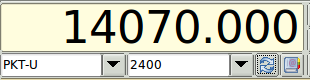

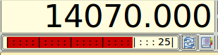
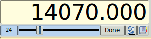
The transition between Mode/Bandwidth and the other control/displays is made using the button just to the right of the bandwidth control.
The transition from either S-meter or Power-meter to the Power Level is make by left clicking on the S-meter or Power-meter.
Debugging
To assist in debugging an xml file you may place the following statement within the body of the <rigdef>...</rigdef> pair.
<DEBUG>true</DEBUG>
fldigi will then record critical events as they occur during the execution of the rigCAT loop. Remove the debug statement from the xml when the file has been proven and before publishing.
You can test an xml to observe the CAT send sequences by inhibiting the actual connection to the serial port.
<NOSERIAL>true/false</NOSERIAL> - default false
The serial i/o events are normally recorded as a sequence of HEX values. This behavior can be changed to record the events as a string of ASCII characters.
<ASCII>true/false</ASCII> - default false
You can use the xml remarks brackets
<!--
...
-->
to surround sections of the xml document to inhibit certain functions if they have already been proven.
You can increase the polling interval to slow things down during debugging.