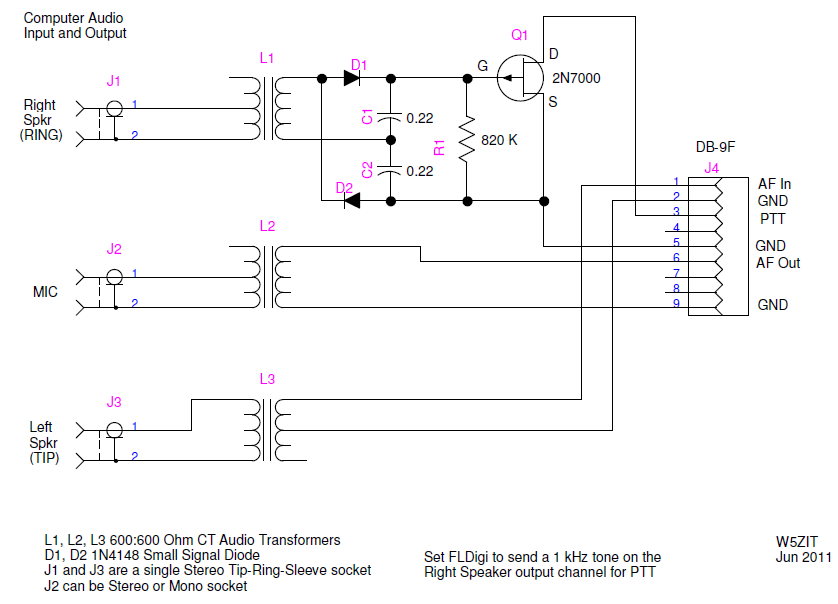
This interface is designed to take advantage of the Right Speaker tone output in FLDigi for actuating the PTT. It is especially useful for interfacing a small notepad with minimal I/O capability to a radio. It has been my experience that complete ground isolation between a laptop and the radio (including eliminating any kind of rig control) provides the minimum QRM to the receiver from the laptop. The Headphone and Mic connections are the only computer connections necessary.
The tone output is coupled through a transformer to maintain complete ground isolation between the computer and the radio. There is no external power required for this interface and an FET is used to provide the PTT output. I use transformers in both the audio input and output paths to complete the isolation.
Note that two of the transformers are wired to the single stereo jack from the Speaker output of the computer. The normal Left Speaker Output (TIP) is used to provide the modulating audio for the radio transmit input while the Right Speaker Output (RING) provides the tone output that drives the PTT circuit. The SHELL of the connector provides the return path for both signals.
Audio from the radio is supplied to the MIC input on the computer for demodulation by the FLDigi program.
Somewhat higher output from the computer is required to reliably operate the PTT circuit and the audio balance control in the computer is used to reduce the output to the radio to the level required for normal modulation. Since the right speaker tone output is not the same audio used to modulate the radio, no signal distortion is caused by the clipping action of the diode rectifiers used in the PTT circuit.
To configure FLDigi to use this interface go to (Configure/Rig Control/Hardware PTT) and check only the (PTT tone on right audio channel) box.