Table of Contents
The RTTY modulator and demodulator have been extensively changed with version 3.21.67. The new design was a cooperative effort of Stefan, DO2SMF, and Dave, W1HKJ with extensive testing performed by Ed, W3NR, and Dick, AA5VU. Chen, W7AY, was a silent contributor to the design by virtue of his excellent technical papers on RTTY modulation and demodulation, which he so generously placed in the public domain.
fldigi can operate on a wide range of RTTY symbol rates and bandwidths. The selection of symbol rate and bandwidth is made on the RTTY configuration tab. The three most common in amateur radio use can be selected from the mode menu. These are
| Mode | Symbol Rate | Typing Speed | Bandwidth |
|---|---|---|---|
| RTTY 45 | 45.45 baud | 6.0 cps (60 wpm) | 270 Hz |
| RTTY 50 | 50.0 baud | 6.6 cps (66 wpm) | 280 Hz |
| RTTY 75 | 75.0 baud | 10.0 cps (100 wpm) | 370 Hz |
These modes were a result of mechanical and electrical designs of the early TTY machines. The 45.45 baud and 75 baud machines were for the US / Canadian market and used 60 Hz synchronous motors. The 50 baud machines were for the European market and used 50 Hz synchronous motors.
fldigi can encode and decode many other symbol rates and bandwidths. "Custom" combinations are set up on the RTTY configuration tab. You probably will never have to do that unless you like experimenting with unusual RTTY modes.
RTTY modulator
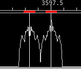
All of the modem signals that fldigi produces are audio signals. That includes the RTTY signal. fldigi can encode and decode an RTTY signal that is anywhere within the passband of the sideband transceiver. It is not limited to the traditional tone pairs around 2100 Hz. Each of the generated Mark / Space signals are on-off-keyed (OOK), bandwidth limited signals. The resultant waveform is not an FM type signal of constant amplitude. Therefore the transmit audio and RF amplifiers must be linear, just like the requirement for PSK signals. There are performance gains using this approach. The principal being a reduction in inter symbol interference which gives much improved performance by the receiver. The waterfall, time domain, and spectrum signatures of the transmitted signal look like this:
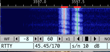
You must operate your transceiver in the USB mode for the fldigi RTTY signal to be the correct polarity. If your transceiver is set to LSB then use the fldigi "Rev" button to reverse the sense of the mark and space signals.
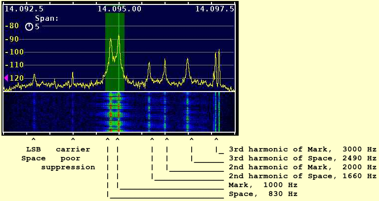
You must maintain transmitter LINEARITY in the AUDIO AMPLIFIERs. Do not think that you can improve performance by over driving the audio input. A good operating procedure for most transceivers is the set the audio level to the level for which there is just barely a hint of ALC. Then reduce the input to 80% of that power level. Over driving an AFSK signal is as disastrous as over driving a PSK signal. This is an actual on air signal that was being over driven (but not on purpose):
Joe also performed a series of tests on an Icom 706 mkIIg transceiver. The results of those tests are very enlightening.
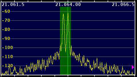
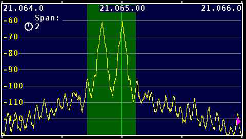
"Two views - the 2 KHz span and a 10 KHz span. The 10 KHz span shows the one failing of the IC-706mkIIg and other rigs with analog modulation - opposite sideband and carrier leakage. This one isn't too bad but one can see carrier at -50 dBc and opposite sideband at -55 dBc +/-. I do use a high audio frequency to minimize harmonic issues.
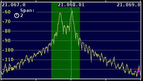
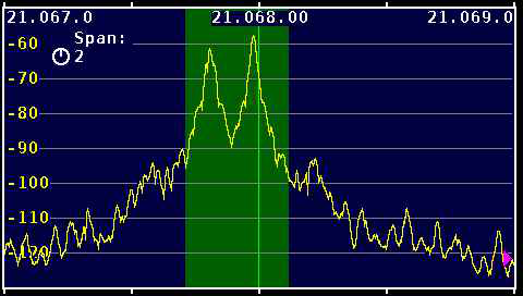
For fun I've attached versions at 70 W in 10K, 5K, and 2K spans. The narrow spans clearly show the benefits of reducing the audio until output power drops 1.5 dB.
Audio was connected to the IC-706mkIIg via the "DATA" jack rather than the mic connector or "Mod In" pin of the ACC jack. Using this input avoids several potential problems - including the constant swapping between mic and digital connections and remembering to turn off the compressor when switching to digital operation. The "Data" input is also 6 dB less sensitive than "Mod in" making it that much less likely that one will significantly over drive the the transceiver and create distortion in the audio stages ahead of the modulator".
The green area is 400 Hz wide.
Transceiver operated in FSK mode
Power: 100 W
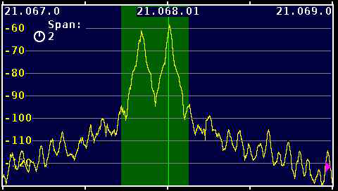
Transceiver in USB, fldigi AFSK audio drive
Space at 2125, Mark at 2295 Hz
Power: 100 Watts, ALC just extinguished
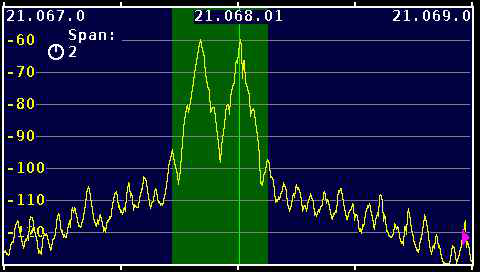
Transceiver in USB, fldigi AFSK audio drive
Space at 2125, Mark at 2295 Hz
Power: reduced to 80 Watts (-1 dB)
Transceiver in USB, fldigi AFSK audio drive
Space at 2125, Mark at 2295 Hz
Power: reduced to 70 Watts (-1.5 dB)
Transceiver in USB, fldigi AFSK audio drive
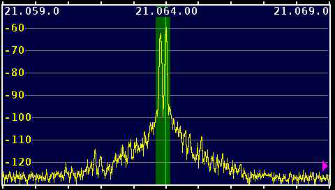
Space at 830 Hz, Mark at 1000 Hz
Power: 70 Watts. The LSB leakage is clearly
seen at approximately -55 dB
Transceiver in USB, fldigi AFSK audio drive
Space at 830 Hz, Mark at 1000 Hz
Power: 70 Watts. The LSB leakage is clearly
seen at approximately -55 dB.
Transceiver in USB, fldigi AFSK audio drive
Space at 830 Hz, Mark at 1000 Hz
Stop Bits set to 2 vice 1.5
Power: 70 Watts. Compare this to image D
RTTY demodulator
Fldigi's demodulator uses a design based on theoretical work published by Kok Chen, W7AY, http://www.w7ay.net/site/Technical/ATC/.
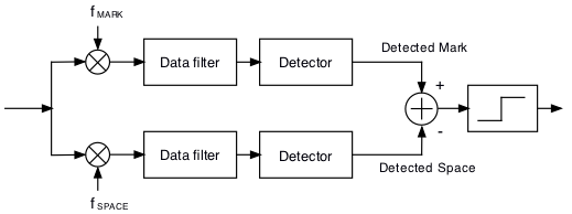
The mark and space signals are converted to base band and then filtered in a low pass filter. Each filter is a variant of Chen's enhanced Nyquist filter. It is implemented using a Fast Overlap-and-Add Fourier Transform.
Each time the baud rate is selected the program must "rebuild" the digital RTTY filter. The filter parameters are optimized for the baud rate.
The detector is an optimized Automatic Threshold Correcting (ATC) type described in Chen's paper.
To start decoding a signal simply left click on the signal and the AFC should lock on to the signal.
The digiscope display will extinguish when the Rx signal level falls below the squelch setting.
Many amateur transceivers offer native FSK support for RTTY. This support also included RTTY-centric filters and optimizations that operators have wanted to use. This native transceiver RTTY support is where the radio itself creates the MARK and SPACE signals but the key up/down and timing is done externally via say a hardware TNC or other device.
It is possible to use fldigi to generate the keying waveform for use with such a transceiver. See Pseudo FSK for a description of how this can be accomplished.
Fldigi also supports a few external hardware devices for FSK-based RTTY support
See nanoIO Interface for additional information on nanoIO and MORTTY interface.
See Navigator Interface for additional information on using the Navigator interface.
See RTTY Configuration Page
Return to Top of Page
Return to Main Page